Gate Design in Thermoset Molding
Because thermoset plastics may be injection molded, the tooling design for a thermoset injection molded part or component must include a runner and gate to allow the thermoset material to flow, or fill, from the molding machine barrel to the mold in order to produce the part. The type of gate used, and its location, can positively or negatively affect a final molded part in its cosmetic appearance and physical dimensions. Proper gate design allows material to flow evenly throughout the tool to produce the molded part, minimizing scrap from unpacked parts or short shots.
While there are many gating options and gate types, there are two ways for a gate to be removed or trimmed, called de-gating: Automatically – by incorporating features in the mold or tool to cut or break off the gate; and Manually – by physically cutting or trimming the gate by hand from an operator or material handler using a file, knife, or other cutting tool after a part has been molded and ejected from the tool.
Examples of Three Common Types of Gating:
Edge Gate – Gated at the edge of a part on a parting line, edge gates are generally used in applications with flat parts, multi-cavitation parts, and parts with thick walls. Edge gates will leave gate vestige or gate marks on the physical part, requiring a manual gate trim secondary operation.
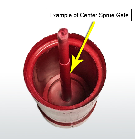
Center Sprue Gate – Center sprue gates are used in single cavity cylindrical parts that must be filled symmetrically to keep roundness specification. As with edge gates, center sprue gates will require manual cutting or trimming of the gate vestige.
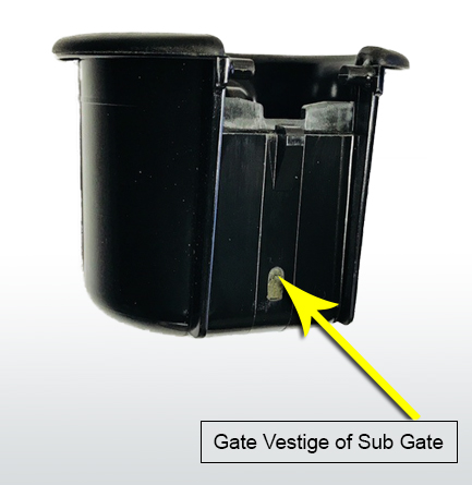
Sub Gate – Sub gates are an automatic style gate designed with features built into the mold so that as the molded part ejects from the mold, the gate trims off any excess material or vestige on the diameter. Location of the sub-gate should be roughly .125” below the parting line to be effective.


